Troubleshooting
Software
Restarting the Device
Besides disconnecting power, restart through your browser at http://BSCIP/restart/, replacing BSCIP with the BSC's current IP address. If Wi-Fi has failed, its access point may be active; it retries the original network every 5 minutes. Connect to the AP as described here and issue the restart.
BMS SoC Differs from the Value Sent to the Inverter
Three possible causes:
-
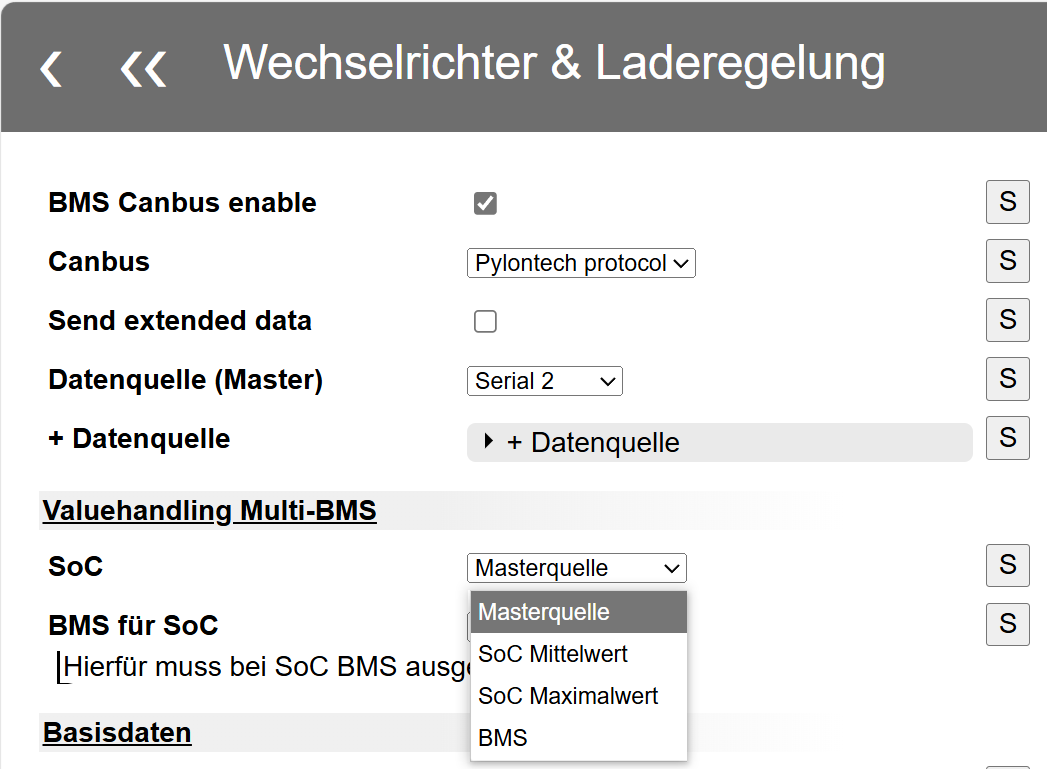
Incorrect SoC source selection. See Valuehandling.
-
A selected SoC source has not sent data for more than 5 seconds and is excluded. SoC uses the remaining available sources. It is included automatically when data returns.
- SoC linearisation is enabled under value adjustments. Under Settings / Interfaces / Data devices / Value adjustments, leave Cellvoltage for SoC 100% and Cellvoltage for SoC 0% empty or disable linearisation when using the BMS's own SoC calculation. See Value Adjustment.
Log Message: “MQTT Queue ist voll”
The MQTT queue is full if the broker cannot process queued data quickly enough. One user encountered this with several applications in a single Docker container; splitting them into separate containers resolved it. Distributing load may help in a similar setup.
Serial Debugging
Special diagnostic firmware can send extended information through the programming interface. It uses Serial 0, so no external RS485 device may be connected there during debugging. The web UI log is disabled in these builds and displays only previous firmware events.
Use a UART/USB converter with 3.3 V logic levels and a PC terminal program. FT232R adapters have worked well; CP340G adapters often work too. Adapters not designed for 3.3 V can permanently damage the controller.
Connect through the three-pin J2 header beside the processor; labels are printed at the PCB's upper left: TX to RX, RX to TX, GND to GND.
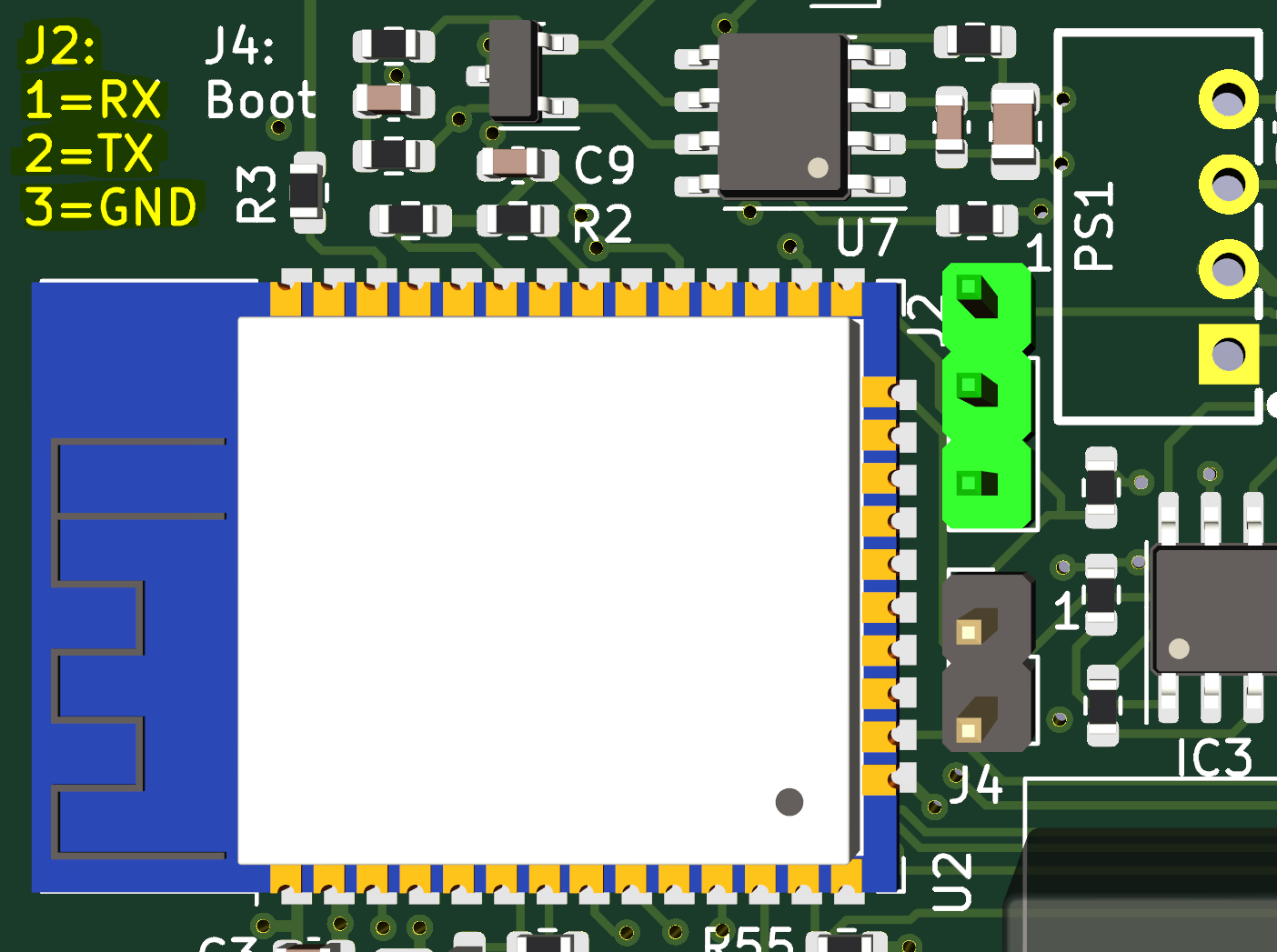
Windows terminals include PuTTY, YAT and HTerm. Find the COM port in Device Manager under Ports (COM & LPT). Use 115200 baud, 8 data bits, no parity, 1 stop bit. Power-cycle the BSC to test whether boot information arrives. Video.
Hardware
Communication with External Hardware Fails
Recheck every connection. Every connector has a PCB-printed pin-1 mark, which must agree with the function label and connected conductor.
Checking CAN Connections
- Termination: Disconnect power from both devices and disconnect their linking cable. Measure resistance between CAN_L and CAN_H at each device: normally 120 ohms per side. Some devices lack built-in termination; if only the BSC has 120 ohms, carefully recheck pin assignments as this is unusual. With both 120-ohm terminations connected together and power still off, the bus should measure 60 ohms.
- Signals: Verify CAN_H to CAN_H, CAN_L to CAN_L and GND between both sides, observing any device-specific connection instructions.
Serial 2 Has Only Timeouts
Check whether J6 is fitted. See J6 for Normal Operation.
Sporadic Serial CRC Errors (HW2.3 and HW2.4)
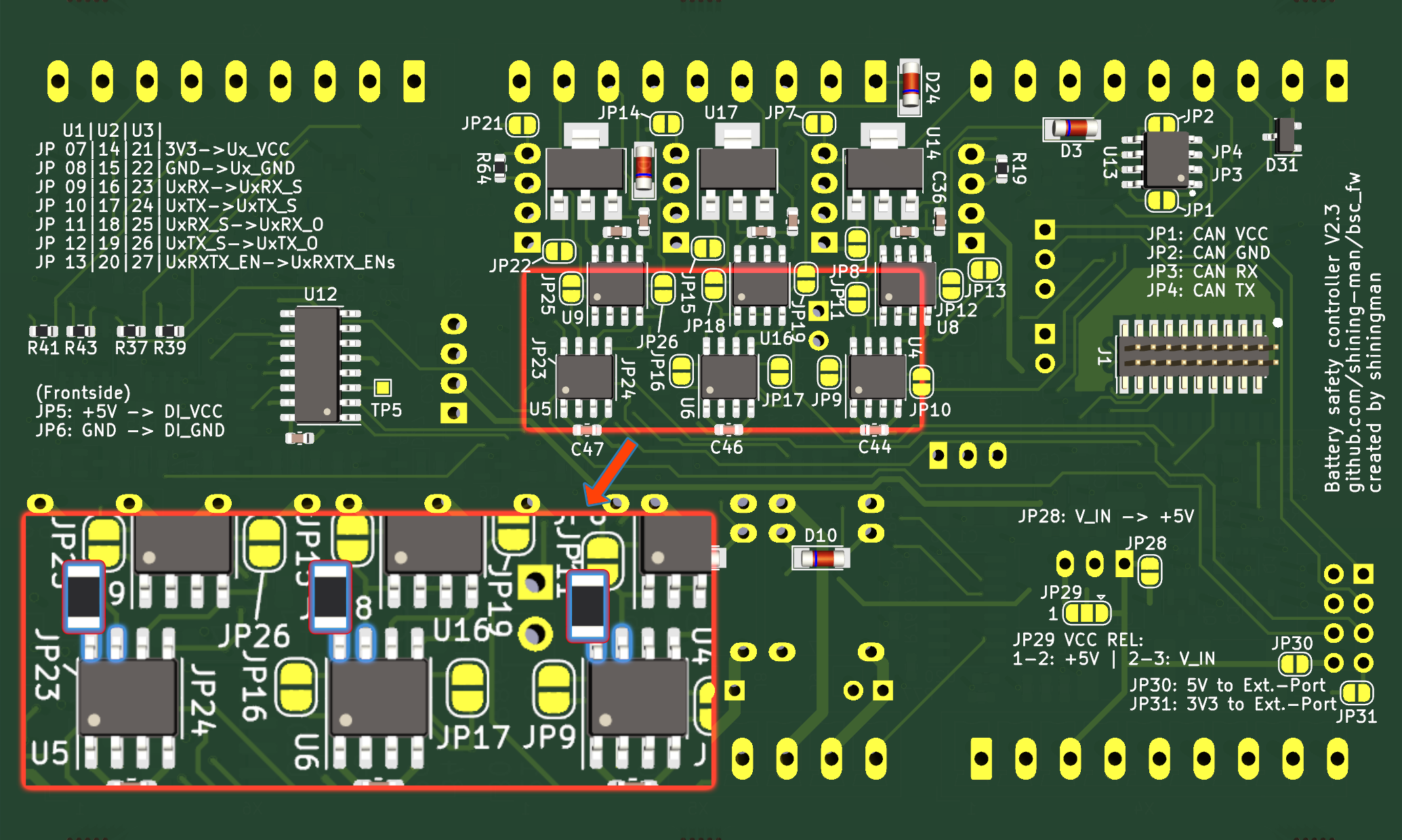
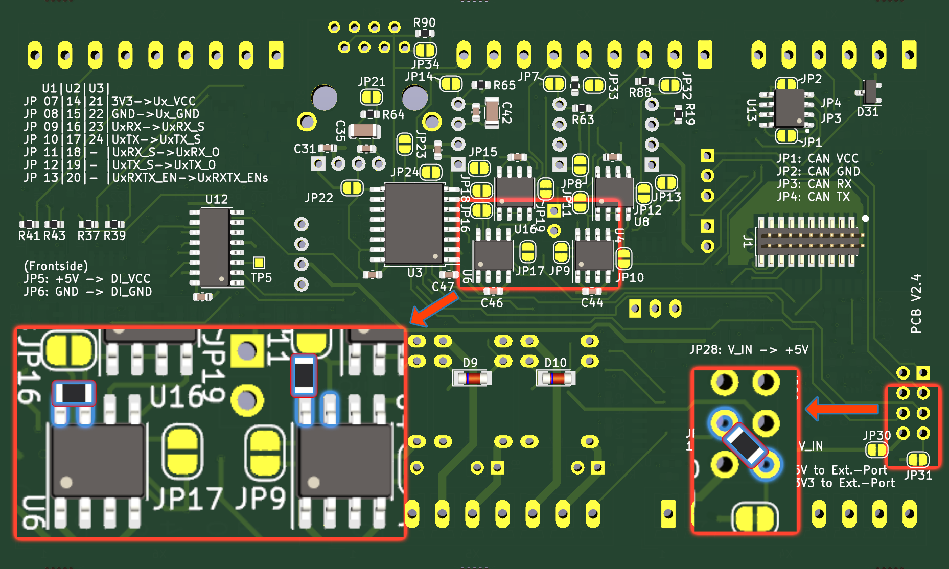
Missing RX pull-ups can leave signals floating. Add 10 kohm pull-up resistors. Package choice depends on soldering skill: 0603 fits between pins, 0805 can also work; vertical placement suits 1206 or 0805; between J3 through-hole pins, 0805 or 1206 works.
HW2.3
Serial 0, 1 and 2: Fit 10 kohms between pins 7 and 8 of U4, U5 and U6 respectively. Higher contact points on each IC can make soldering easier. PCB underside:
HW2.4
Serial 0 and 1: Fit 10 kohms between pins 7 and 8 of U4 and U6. For U4, the illustrated contact location may be easier.
Serial 2: Fit 10 kohms between pins 6 and 7 of J3; a through-hole resistor also works. PCB underside:
CAN_GND Connection (HW2.3)
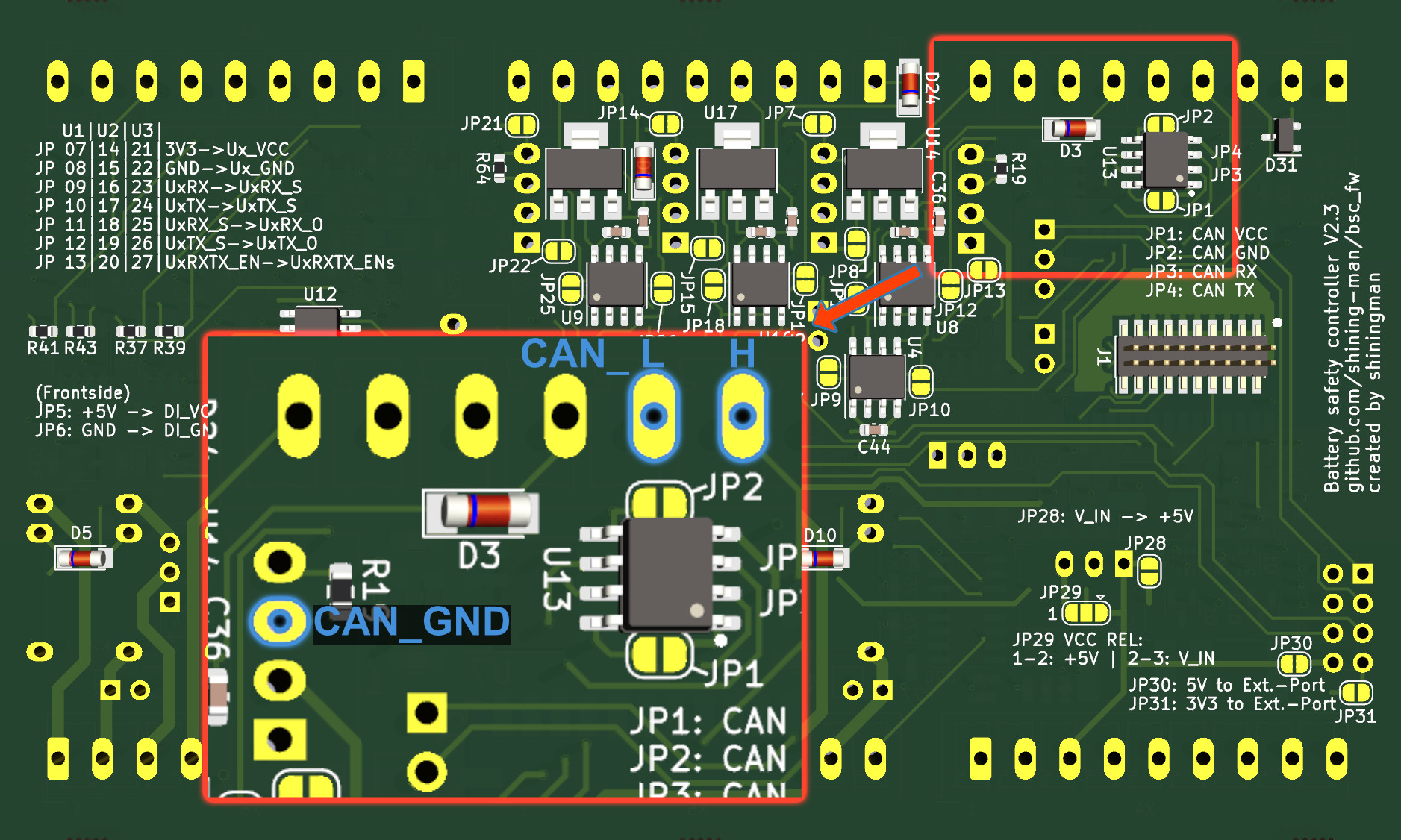
The screw terminals expose CAN_L and CAN_H but not CAN_GND. Obtain CAN_GND from the voltage regulator pins on the PCB underside as shown: