Inverter
Configure CAN communication and processing of measurements sent to the inverter: SoC, total voltage, current and temperature. Source selection determines which devices provide each value; multiple sources can be aggregated.
General
-
BMS Canbus enable
-
Canbus protocol
-
Send extended dataDo not enable when using a Cerbo GX!
-
Data source
-
- BMS CANbus enable: Enables CAN communication. When disabled, no inverter data is sent.
- CANbus protocol: Select the inverter protocol. Most inverters require Pylontech.
- Send extended data: Adds CAN packets. Only usable with Victron and the required driver. Not recommended for CerboGX, as communication problems can occur.
- Data source: Data devices used by all charge controls; their values are processed and sent to the inverter. Depending on enabled controls, these sources must provide cell voltages. Sources used only for total voltage, current or SoC (e.g. a shunt) belong under Valuehandling, not here.
Group Devices
With group devices enabled, select battery packs (groups) instead of individual data devices.
Free Firmware
Also select a master data source here. Its battery voltage is sent to the inverter.
Valuehandling
Select sources independently for SoC, total voltage and total current, and select how multiple sources are aggregated.
- SoCDomainSoC source
-
Aggregation
- VoltageDomainTotal voltage source
-
Aggregation
- CurrentDomainTotal current source
-
Aggregation
Free Firmware
Only SoC aggregation can be configured here in the free firmware.
Domain: Auto chooses data or enabled group devices automatically; Data devices lists configured data devices; Group devices lists groups and is available only when groups are enabled.
SoC source: Select the data or group devices providing SoC. With one source, only its value determines system SoC.
SoC aggregation: Average, Maximum, Minimum, BMS (first selected data device), or Capacity-weighted using pack capacities from Basic Data.
Capacity-Weighted Calculation
Each pack contributes in proportion to its capacity:
SoC = sum(pack SoC × pack capacity) / sum(pack capacities)
For example, pack 1 at 300 Ah / 80 % and pack 2 at 100 Ah / 40 % give 70 %. The unweighted average is 60 %, the maximum 80 %. Internally, calculation uses hundredths of a percent; the result is rounded to whole percent.
Missing Capacity
Packs with 0 Ah are excluded from capacity weighting. If all selected packs have no capacity, a default SoC of 100 % is assumed.
The default per-pack capacity is 280 Ah, so unchanged packs use that value. Other aggregation modes do not use capacity: average takes the arithmetic mean, maximum/minimum take the corresponding extreme, and BMS uses the first selected device.
Total voltage source / aggregation: With one source, use its voltage directly. With several, choose average, maximum or minimum. Send the resulting voltage to the inverter.
Total current source / aggregation: With one source, use its current directly. With several, choose sum, average, maximum or minimum. Send the result to the inverter.
Basic Data
-
Absorption charge voltageVAbsorption charge voltage is an elevated voltage used to reach a fully charged state.
-
Float charge voltageVFloat voltage is applied when the configured Cut-Off condition is met.
-
Float charge voltage SoC%When SoC falls below this value, charging switches from float to absorption voltage.
-
Maximum charging currentA
-
Maximum discharging currentA
-
Set SoC to 100
-
Set SoC to 0
Batterypack settings
- Data device 1
Charge current per packADischarge current per packACapacityAh- Data device 2
Charge current per packADischarge current per packACapacityAh
-
Absorption charge voltage: Voltage used to bring batteries to a nearly full state. Do not hold it permanently: doing so can harm service life and performance. For LiFePO4 cells, a sustained low current is a suitable point to move to float. Charge-Current Cut-Off automates this; without it, the battery may remain at absorption voltage, which can cause long-term damage.
Float charge voltage: The documentation uses this as the resting/holding voltage near open-circuit voltage (OCV), rather than the higher absorption voltage, to avoid continuing to charge a full battery.
Entering Float
Only Charge-Current Cut-Off or Autobalance switches the system to float.
Float voltage SoC: When SoC drops below this value, return from float to absorption to start a full charge again.
Choose the Threshold Carefully
Too high a threshold can immediately return the system to absorption. Inaccurate BMS SoC can also distort transitions; an external shunt is recommended for precise SoC.
Profiles
Absorption voltage, float voltage and float voltage SoC support P1/P2. With profile switching enabled, the active profile's values apply.
- Maximum charging current: Upper limit sent to the inverter to prevent charging overload.
- Maximum discharging current: Upper limit sent to the inverter to avoid excessive discharge current.
- Set SoC to 100 / 0: Forces system SoC to the selected value when an assigned trigger is active.
Batterypack Settings: Per data device, configure charge current (0–500 A), discharge current (0–500 A) and capacity (1–1000 Ah). Capacity also feeds weighted SoC.
When a BMS disconnects a pack, remaining packs must carry its share. The BSC adjusts the transmitted limit to the number of active packs, never exceeding the configured system maximum. Example: with three packs rated 100 A each and a 180 A system charge limit, losing one leaves 200 A pack capability, so the limit stays 180 A. Losing another reduces it to 100 A. Discharging works analogously.
Trigger-Based Limits
-
Set charge power to 0
-
Set discharge power to 0
- Trigger-based current limitsWhile the trigger is active, these values act as upper limits. They do not override the configured maximum values!
- Rule 1
-
Trigger
- Current limitsMaximum charging currentAMaximum discharging currentA
- Rule 2
-
Trigger
- Current limitsMaximum charging currentAMaximum discharging currentA
-
- Charging power to 0: Sets charge current to 0 A if any assigned trigger (1–27) is active.
- Discharging power to 0: Corresponding discharge limit.
- Trigger-based current limits: 3 rules, each with selected triggers and maximum charging/discharging currents (0–1000 A). These are additional upper limits, not overrides of system limits: the smaller value applies.
Charge Voltage Ramp
Changes in charge voltage, e.g. float to absorption, occur gradually instead of abruptly, reducing voltage steps and system stress.
Firmware Availability
Not available in every firmware version.
- Adjusts charge voltage to the new setpoint.
Time-ramp mode: time-based changes of 100 mV per step.
Auto mode: increases voltage using the time ramp; decreases it based on the current battery voltage. During a decrease, charging current is temporarily set to 0 A until the target voltage is reached.-
Mode
-
Time per voltage steps
-
Mode:
- Off: Apply the target immediately.
- Time ramp: Move in 100 mV steps at the configured interval (default 15 s) in either direction until the target is reached.
- Auto: Ramp upwards by time; ramp downwards using measured battery voltage, temporarily forcing charge current to 0 A.
Time per voltage step: 1–240 s, default 15 s, per 100 mV step.
Auto Mode in Detail
Upwards, increase by 0.1 V per interval while charging remains allowed. Downwards:
- A lower target (e.g. float) starts the downward phase.
- While battery voltage exceeds the target, force charging current to 0 A, regardless of other current limits.
- Each 1 s control cycle sets the setpoint to measured battery voltage, rounded to 0.1 V, but never above its previous value.
- Once battery voltage reaches or falls below the target, apply the exact target and release charging current again.
Example: target changes from 56.0 V to 54.0 V at a measured 56.0 V. Charging immediately becomes 0 A. As voltage falls (56.0 → 55.7 → 55.4 → …), the setpoint follows in 0.1 V resolution. At 54.0 V, release current. A later target increase uses the time ramp.
Special Cases
- Without a valid battery voltage measurement, apply the target immediately.
- If voltage is already below the new target when lowering starts, apply it immediately without blocking current.
- Changes caused by the dynamic charge voltage offset also count as target changes. The ramp is applied last, after target adjustments.
- The downward phase lasts as long as battery voltage takes to reach the target, with no charging and possibly a load.
When enabled, the ramp acts on every setpoint change.
Battery Temperature
Select the data device or extended sensors providing battery temperature to the inverter.
-
SourceInterpretation depends on mode:
Group devices disabled: data-device index
Group devices enabled: battery-pack index -
Sensor type
-
Sensor numberData-device sensors: 0-5
Extended sensors: 0-31
-
- Source: Data device; unused = 255 disables temperature transmission. With groups, select a group instead.
- Sensor type (groups only): Data-device sensors 0–5 or extended sensors 0–31.
- Sensor number: Number within the selected type.
Free Firmware
Temperature always comes from the master source.
Cell Temperature
Select which sensors of the configured data sources determine minimum and maximum cell temperature transmitted to the inverter.
- Uses the data devices selected under 'Data source'.
-
Sensors
-
Firmware Availability
Cell temperature selection is not available in every firmware version.
Inverter Alarms
-
High battery voltage
-
Low battery voltage
-
High Temperature
-
Low Temperature
-
Report High battery voltage, Low battery voltage, High Temperature or Low Temperature when at least one of the alarm's assigned triggers (1–27) is active.
SoC Triggers
Four rules activate triggers above or below a configured SoC, e.g. for external devices.
- Activate a trigger when the SoC rises above or falls below a specified value.
- Rule 1
-
Trigger
-
SoC - trigger on%
-
SoC - trigger off%
- Rule 2
-
Trigger
-
SoC - trigger on%
-
SoC - trigger off%
SoC trigger on: Activation threshold, default 95 %. SoC trigger off: Deactivation threshold, default 80 %.
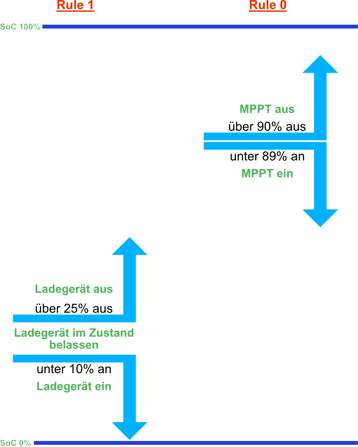
- Rule 0, MPPT controller relay: On at <= 89 %, off at >= 90 %.
- Rule 1, off-grid charger relay: On at <= 10 %, off at >= 25 %. Starting from 0 %, it charges until 25 %, then remains off until 10 % or below: 15 percentage points of hysteresis.