Testing Without BSC Hardware
General
This build is not recommended for production use. It is a temporary test platform for exploring the project's scope. Third-party boards may cause stability problems. Original hardware is tested, purpose-built and galvanically isolated, especially important with BMS units that disconnect the negative power path.
Problems with Negative-Switching BMS Units
Some BMS units disconnect the negative path during a fault. If an alternative ground path exists, for example BMS → RS485 → BSC → inverter, battery current can flow through thin signal wires, creating a cable-fire hazard. The inverter may not notice and may continue drawing current. Use galvanically isolated modules for these BMS types.
Hardware Modules
All modules must support the microcontroller's 3.3 V logic and supply.
ESP32 Microcontroller
Module Information
An ESP32 development kit can be used for initial testing. NodeMCU boards with an ESP32-DOWx chipset (e.g. ESP-WROOM-32), such as Berrybase NMCU-ESP32, are compatible.
Power Supply
NodeMCU power supplies can be inadequate and cause instability:
- Connect a quality 3.3 V / >= 1.5 A supply directly to 3.3 V and GND.
- Add capacitors between these pins, for example 220 nF ceramic, 22 µF and 470 µF electrolytic.
Module Connection Requirements
Use suitable level converters for external hardware. ESP32 UART is 3.3 V logic, not RS485. Incorrect connection can destroy the controller or connected equipment.
GPIOs
Communication module data pins; connect a Seplos BMS to Serial 2.
| Interface | RX | TX |
|---|---|---|
| Serial 0 | GPIO 16 | GPIO 17 |
| Serial 1 | GPIO 23 | GPIO 25 |
| Serial 2 | GPIO 35 | GPIO 33 |
| CAN | GPIO 5 | GPIO 4 |
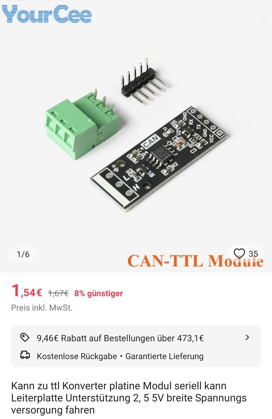
CAN Converter
The module below has worked reliably in one prototype and is available from several suppliers. Connect CANH, CANL and GND.