Charging
Configure BSC charge control: limits based on cell voltage, cell voltage difference, SoC and temperature, plus Autobalance for periodic balancing and Charge-Current Cut-Off to finish charging. Percentage limits refer to Basic Data. Communication, sources and basic values are configured under Inverter.
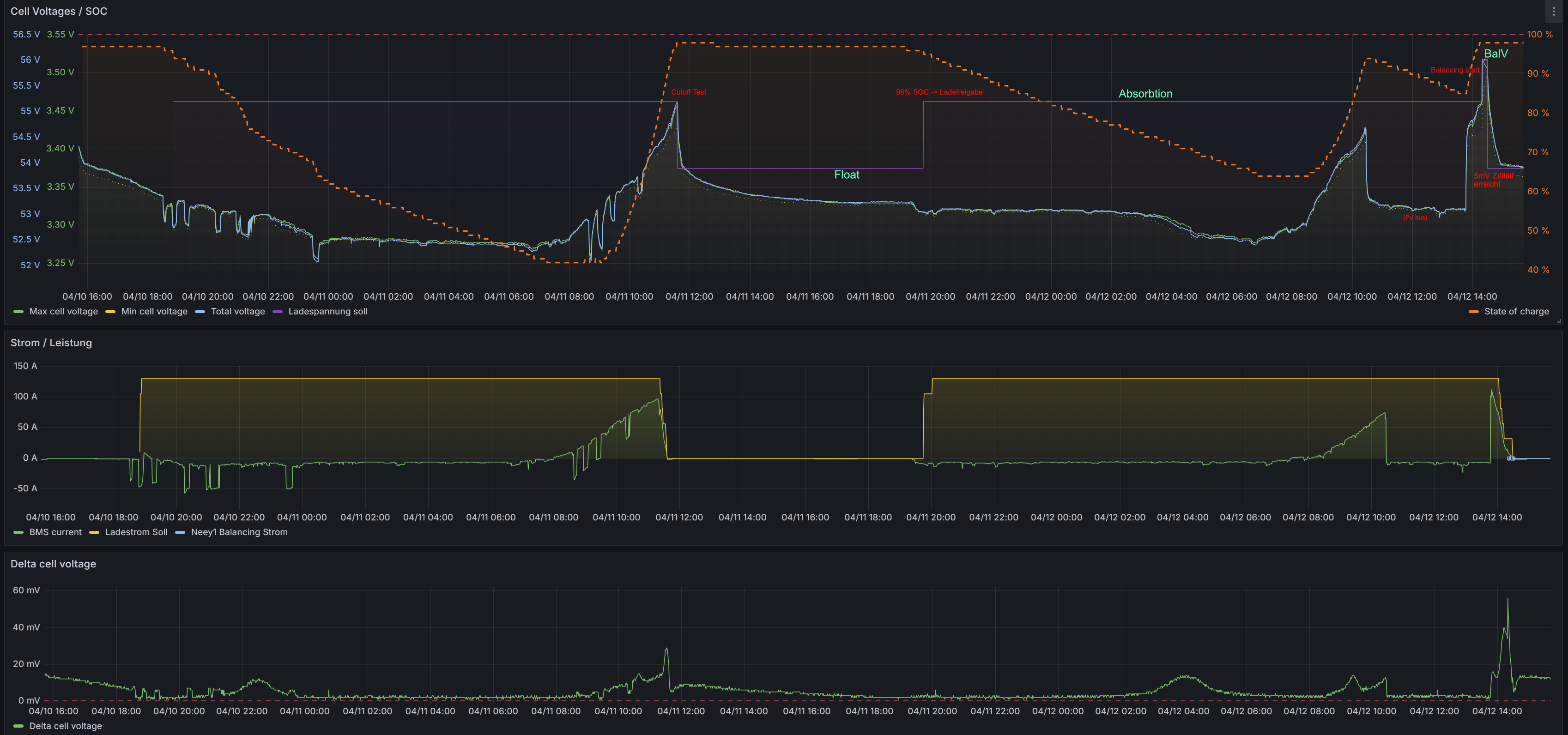
Example charge cycle with balancing, float and absorption voltage, visualised in Home Assistant/Grafana:
Dynamic Charge Voltage Offset
Adjusts charging voltage linearly with charging current, using the lowest pack charging current. This can compensate cable voltage drop.
- Dynamically adjusts charge voltage according to charging current.
The offset depends linearly on current. The lowest charging current of the battery packs is used for the calculation.-
On/Off
-
CurrentACurrent at which the maximum offset is added.
-
Min. OffsetmV
-
Max. OffsetmV
-
- On/Off: Enables the function.
- Current [A]: Current where maximum offset applies.
- Minimum offset [mV]: Added at 0 A.
- Maximum offset [mV]: Added at the configured current, default 500 mV.
Excessive Charging Current per Pack
- Reduce charging current if a pack exceeds its charge-current limit
-
On/Off
-
Dynamically adjusts charging current to keep each pack within its maximum.
- Off: Disabled.
- On: Uses configured per-pack currents.
- C-Rate: Calculates each pack's current from its configured capacity (Ah) and temperature profile (C-rate = current/capacity). Without a capacity, limits current to 0 A.
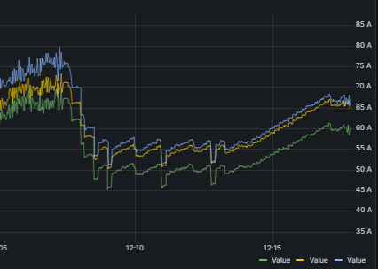
Green is pack 1, yellow pack 2 and blue pack 3. In the middle, pack 1's limit is temporarily reduced to 50 A. The BSC dynamically reduces charging and holds that pack at its new limit.
Cell-Voltage-Dependent Charge Reduction
Progressively reduces current when a cell exceeds a defined voltage, approaching the target gently and avoiding individual-cell overcharging.
-
On/Off
-
Start above cell voltagemVReduction starts when the highest cell voltage exceeds this value.
-
Maximum cell voltagemVWhen the highest cell voltage exceeds this value, charging is limited to the minimum charging current.
Note: this value must exceed the start cell voltage.
Warning: during active Autobalance, this voltage is replaced by the Autobalance maximum cell voltage! -
Maximum cell voltage (float)mV0 = disabled: the maximum cell voltage is also used during float charging.
-
Minimum charging currentA
-
- On/Off: Enables reduction.
- Start above cell voltage [mV]: Starts when the highest cell exceeds this value.
- Maximum cell voltage [mV]: At this voltage, only the minimum current remains. Must exceed start voltage.
- Maximum cell voltage (Float) [mV]: Separate float threshold. 0 disables it and uses the normal maximum during float too.
- Minimum charging current [A]: Lower current bound at maximum cell voltage.
Autobalance Override
Once enabled Autobalance reaches Wait for start cell voltage, its maximum cell voltage replaces this rule's normal maximum. See Autobalance.
Cell Voltage Difference Reduction
Reduces current when the difference between highest and lowest cell voltage becomes excessive, allowing a balancer to work and preventing further divergence.
-
On/Off
-
Start above cell voltagemV
-
Start above cell differencemV
-
Reduction per additional mV of differenceAReduction is relative to the configured maximum current
-
- On/Off: Enables the rule.
- Start above cell voltage [mV]: Voltage where difference monitoring/current reduction becomes active.
- Start above difference [mV]: Highest-to-lowest cell difference in a pack where reduction starts.
- Reduction per additional mV [A]: Current reduction per millivolt beyond the configured difference threshold, based on the maximum charging current.
SoC-Dependent Charge Reduction
Progressively reduces current at or above the configured SoC.
- This rule is disabled as soon as Autobalance waits for the start cell voltage.
-
On/Off
-
Reduce from SoC%
-
Reduce by x A per 1%AReduction is relative to the configured maximum current
-
Minimum charging currentA
-
- On/Off: Enables the rule.
- Reduce from SoC [%]: Starting SoC.
- Reduce by x A per 1 %: Reduction for each additional SoC percentage point, based on the configured maximum.
- Minimum charging current [A]: Current floor.
Autobalance
This rule is automatically disabled once Autobalance waits for start cell voltage.
Temperature-Dependent Charge Reduction
Up to 4 separately configurable rules progressively limit charging using only selected data/group sources. Cold-side reduction uses the minimum, hot-side reduction the maximum selected temperature. Rules can reduce current as temperatures rise or fall.
Firmware Availability
Not available in every firmware version.
- Uses the sources from the active data source (data devices or group devices).
Control uses the appropriate extreme for the direction: the minimum temperature when reducing from warm to cold, the maximum when reducing from cold to warm.- Temperature rules
- Rule 1
-
On/Off
-
Data-device sensors
-
Extended sensor sources
-
Extended sensors 0-31
-
Reduction start°C
-
Reduction end°C
- Data-device sensors: Select sensors 0–5.
- Extended sensor sources / sensors 0–31: Select additional data/group sources and their extended sensors.
- Reduction start: Temperature where reduction starts; may be higher or lower than the end.
- Reduction end: Temperature where current becomes 0 A. A value below start produces cold-side reduction.
Rising temperatures (start < end): Below start, full current; between thresholds, linear reduction; at/above end, 0 A. Example: 100 A, start 20 °C, end 40 °C gives 100 A at 20 °C, 50 A at 30 °C, 0 A at 40 °C.
Falling temperatures (start > end): Above start, full current; between thresholds, linear reduction; at/below end, 0 A. Example: 100 A, start 40 °C, end 20 °C gives 100 A at 40 °C, 50 A at 30 °C, 0 A at 20 °C.
Current = maximum current × (end temperature − current temperature)
          / (end temperature − start temperature)
Temperature-Profile Charge Reduction
A 10-point profile assigns a maximum C-rate to each temperature. It limits charging in cold or hot conditions. Values are linearly interpolated; outside the profile, the first/last point applies.
- Uses the sources from the active data source (data devices or group devices).
-
On/Off
-
Data-device sensors
-
Extended sensor sources
-
Extended sensors 0-31
-
Temperature profile
Show values
X (°C) Y (C) 0 0 5 0.1 10 0.2 15 0.4 20 0.6 25 1 45 0.5 50 0.25 55 0.2 60 0
-
Configuration
- On/Off: Default off.
- Sources: Uses the active data/group sources. Select data-device sensors 0–5, extended sources and extended sensors 0–31. With no sources selected, the function has no effect.
- Profile: 10 points, temperature 0–60 °C in 0.1 °C steps, C-rate 0–1 C in 0.01 C steps.
Choosing Minimum or Maximum Temperature
Find the minimum and maximum over all selected sensors. Use the temperature of the profile point with the highest C-rate as a reference. If the measured minimum is below this reference, use that minimum; otherwise use the maximum.
Current Calculation
Interpolate the C-rate between adjacent points. Below the first/above the last temperature, use that endpoint. If multiple points have the same temperature, the first counts.
Allowed current is C-rate × capacity (Ah), using the sum of capacities of active packs whose data is no older than 5 s (Batterypack Settings). With 0 Ah, current is 0 A. Cap the result at maximum charging current and round to 0.1 A.
Examples: Default Profile, 100 Ah
- Sensors 12 °C and 18 °C: minimum 12 °C is below the 25 °C reference. Between 10 °C / 0.20 C and 15 °C / 0.40 C, interpolate 0.28 C → 28 A.
- Sensors 28 °C and 32 °C: minimum exceeds the reference, so use maximum 32 °C. Between 25 °C / 1.00 C and 45 °C / 0.50 C, interpolate 0.825 C → 82.5 A.
- Below 0 °C: first point 0.00 C → 0 A.
- Above 60 °C: last point 0.00 C → 0 A.
Interaction with Other Rules
The BSC evaluates every active limit, including cell voltage, SoC, cell difference, temperature rules, Cut-Off and per-pack limits, then uses the lowest. The temperature profile remains active during Autobalance. C-Rate mode of per-pack current control also uses this profile, with each pack's own capacity and pack-current ceiling.
Voltage Control for Charging Current Limitation
Dynamically adjusts charge voltage to keep current within the configured corridor. Outside that corridor it corrects voltage; additionally, the transmitted current limit is set to 0 A. This can limit charging to a chosen SoC to extend battery life.
Firmware Availability
Not available in every firmware version.
- Dynamically adjusts charge voltage to keep charging current within a defined range. A charge-current limit of 0 A is sent to the inverter at the same time.
This rule operates only when Autobalance is not active.-
On/Off
-
Active from (SoC)%
-
Control corridor (±)A
-
- On/Off: Always on, off, or enabled only by a selected trigger (1–27), e.g. seasonal home automation.
- Active from SoC: Starting SoC, default 80 %.
- Control corridor (±): Permitted current range, default 10.00 A. No adjustment within it; outside it, voltage is adjusted.
Autobalance Takes Priority
This function operates only when Autobalance is not active.
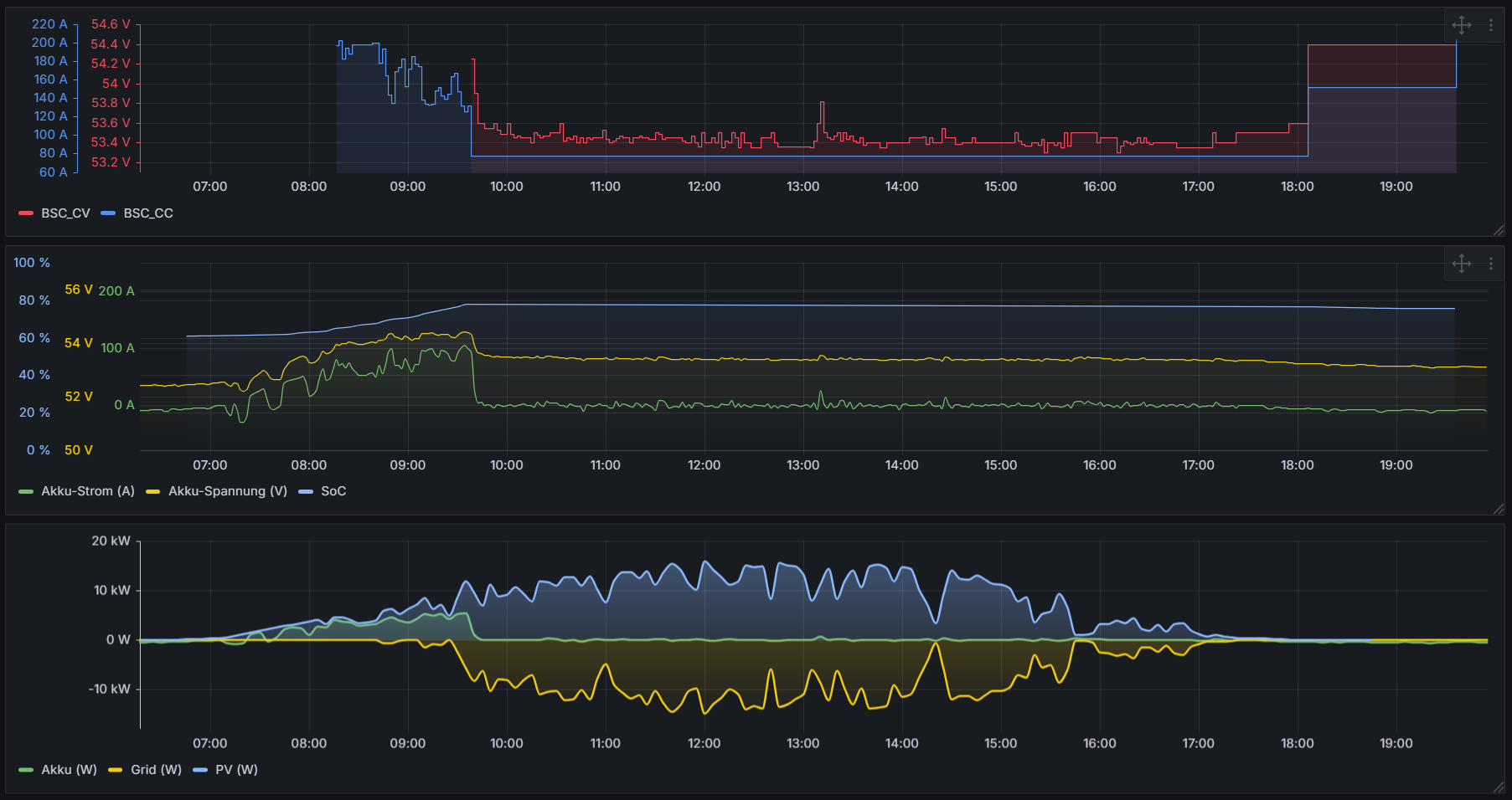
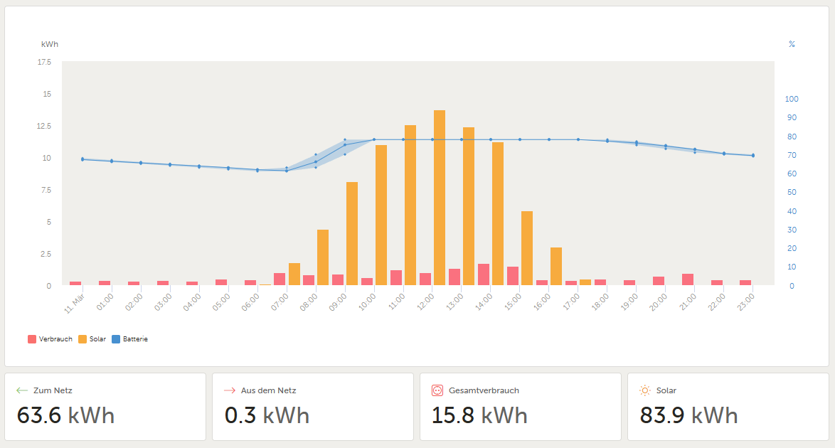
The diagrams show a Victron system with voltage control: current is limited, excess energy feeds into the grid instead of the battery, and SoC stays nearly constant.
Autobalance
Automates periodic cell balancing by raising charge voltage into the range where the BMS's own balancers or external balancers equalise cell voltages.
The BSC Does Not Balance Cells Itself
The BSC has no cell-level passive or active balancing circuits. It only raises voltage to the configured balance charge voltage, enabling BMS passive balancers or external active balancers such as NEEY to operate.
See Interaction with Other Charge Controls for coordinated or suspended rules.
Changes in V0.10.0: New Balance cell voltage combines with Cell difference finished to define the target. Maximum cell voltage (formerly Balance cell voltage) now defines the end voltage of current reduction during balancing. Run-on time replaces Minimum balance time. Skip ‘Wait for charge voltage’ is new. Sending balance voltage once the start time is reached is now standard, not an option.
-
On/Off
-
Start Autobalance (trigger)
-
Balance intervalTNumber of days between balancing cycles.
Note: Charge-Current Cut-Off is disabled while Autobalance is balancing!
The correct number of cells must be configured in Serial settings! -
Start cell voltagemVCell voltage that must be reached before the process starts.
-
Balance charge voltageVDuring Autobalance, maximum charge voltage is raised to this value.
-
Maximum cell voltagemVMaximum cell voltage at which charging current reaches its reduced minimum during Autobalance.
-
Balance cell voltagemVCell voltage that must be reached together with the cell difference target ('Cell difference finished') for balancing to be considered complete and to enter 'Wait for charge voltage'.
-
Cell difference finishedmVBalancing is complete when the configured cell voltage difference is reached.
-
Run-on timeMinAfter balance charge voltage is reached, balancing continues for this run-on time.
-
TimeoutMinAbort the balancing cycle if it has not finished within this time.
-
Advanced options
-
Start Autobalance (trigger): Starts immediately while waiting for the next interval. Manually return the trigger to low after starting.
Balance interval: Time between balancing cycles.
Start criteria: The interval expires (or the start trigger activates), then the highest cell voltage of configured data devices must reach the start cell voltage.
Balance charge voltage: Raised system voltage used during balancing. Sent to the inverter from Wait for start cell voltage onwards.
Maximum cell voltage: Upper cell voltage used as the current-reduction endpoint during balancing.
Balance cell voltage / Cell difference finished: The target is reached when the highest cell voltage reaches the balance cell voltage AND the greatest cell difference does not exceed the configured tolerance. The state then becomes Wait for charge voltage.
Run-on time: Starts when pack voltage reaches 99 % of balance charge voltage. Balancing ends only after this timer expires, then voltage returns to float.
Timeout: Aborts a cycle that exceeds the configured maximum time. The state becomes Wait for next day, with a 12-hour wait before retrying.
Advanced Options
- Return to ‘Wait for start cell voltage’ if below start voltage: Resets the state and running timers when the highest cell falls below the start threshold.
- Disable Cut-Off from ‘Wait for start cell voltage’: Disables it earlier. Without this option, Cut-Off is disabled from Wait for cell voltage/difference.
- Skip ‘Wait for charge voltage’: After the balance target is reached, enter run-on immediately and start its timer. The 99 % pack-voltage requirement and fallback are omitted.
Timing Notes
After restarting the BSC, there is no interval delay before the first balance cycle. The configured interval starts after the first cycle. Starting at 22:00 with a 5-day interval means the next due time is the evening of day five, not its morning; without solar energy then, balancing waits for a following sunny day. Run-on time can help some BMS units, e.g. Seplos, synchronise to SoC 100 %.
MQTT States: /Inverter/autoBalState
| State | Meaning |
|---|---|
| 0 | Autobalance disabled |
| 1 | Wait for start day; interval running |
| 2 | Incomplete cycle; wait 12 h before retry |
| 3 | Due; wait for start cell voltage |
| 4 | Start voltage reached; wait for balance cell voltage and cell difference target |
| 5 | Balance target reached; wait for pack voltage >= 99 % of balance charge voltage |
| 6 | Charge voltage reached; run-on timer running |
Sequence: Enable → wait for start day → interval elapsed or trigger → wait for start cell voltage → highest cell reaches start → wait for cell voltage/difference → balance target reached → wait for charge voltage → pack reaches 99 % → run-on → timer expires → cycle complete and wait for next start day.
Other transitions: Timeout from states 4–6 aborts to the 12-hour wait. Optional low-start-voltage fallback from 4–6 returns to state 3, resetting timers. During run-on, falling below 99 % returns to state 5, unless Skip wait is enabled.
State Diagram
stateDiagram-v2
    s0: Off
    s1: Wait for start day
    s2: Wait 12 hours
    s3: Wait for start cell voltage
    s4: Wait for balance voltage and difference
    s5: Wait for pack charge voltage
    s6: Run-on timer
    s0 --> s1: Enable
    s1 --> s3: Interval elapsed or start trigger
    s2 --> s3: 12 h elapsed or start trigger
    s3 --> s4: Start cell voltage reached
    s4 --> s5: Balance target reached
    s4 --> s6: Target reached and skip-wait option
    s5 --> s6: Pack voltage at least 99 percent
    s6 --> s5: Below 99 percent unless skip-wait
    s4 --> s3: Optional low-start-voltage fallback
    s5 --> s3: Optional low-start-voltage fallback
    s6 --> s3: Optional low-start-voltage fallback
    s4 --> s2: Timeout, set float
    s5 --> s2: Timeout, set float
    s6 --> s2: Timeout, set float
    s6 --> s1: Run-on finished, set float
Start Autobalance (trigger): Available in some firmware versions; starts while waiting for the interval. Reset the trigger to low afterwards.
Balance interval: Days between cycles; the historical example uses 5 days, range 1–30 days. Set the correct cell count in Serial settings.
Start cell voltage: Highest cell voltage required to start; historical example 3300 mV, range 2500–5000 mV.
Minimum balance time: Minimum balancing duration even if cell voltages are already equal. Example 0 minutes, range 0–600 minutes.
Balance charge voltage: Raised system voltage while balancing; historical example 55.20 V, range 20–60 V, step 0.1 V.
Balance cell voltage: Maximum individual cell voltage during balancing; historical example 3450 mV, range 2500–5000 mV. This older parameter is not the V0.10.0 finish-target parameter.
Cell difference finished: Ends the balancing target phase when the greatest difference reaches or drops below this value. Example 5 mV, range 0–50 mV.
Timeout: Aborts an unfinished cycle; historical example 60 minutes, range 0–600 minutes.
Advanced options (not available in every version): send balance voltage as soon as the start time is reached; return to Wait for start cell voltage and reset timers if voltage falls below start; disable Cut-Off already in that waiting state.
After completion, voltage returns to float. There is no interval delay before the first balance after restart. A five-day interval from 22:00 becomes due in the evening, possibly waiting until solar energy is available the next day. Minimum time can help BMS units such as Seplos reach SoC 100 %.
MQTT /Inverter/autoBalState: 0 = off; 1 = wait for next start; 2 = unfinished, retry next day; 3 = due, wait for start cell voltage; 4 = balancing active; 5 = cell difference reached but pack charge voltage not reached; 6 = charge voltage reached, wait for minimum time.
State Diagram
stateDiagram-v2
    s0: Off
    s1: Wait for start day
    s2: Retry next day
    s3: Wait for start cell voltage
    s4: Balancing
    s5: Wait for charge voltage
    s6: Finish minimum balance time
    s0 --> s1: Enabled
    s0 --> s2: Enabled with unfinished cycle
    s1 --> s3: Due
    s2 --> s3: Due
    s3 --> s4: Start cell voltage reached
    s4 --> s5: Cell difference reached
    s4 --> s6: Charge voltage reached and minimum timer started
    s5 --> s6: Minimum timer started
    s4 --> s3: Optional low-start-voltage fallback
    s5 --> s3: Optional low-start-voltage fallback
    s6 --> s3: Optional low-start-voltage fallback
    s4 --> s2: Timeout
    s5 --> s2: Timeout
    s6 --> s0: Minimum time elapsed, set float
Interaction with Other Charge Controls
During balancing, the BSC suspends or adjusts its own controls that would otherwise prevent reaching the balancing voltage range:
- SoC reduction is disabled from Wait for start cell voltage.
- Cut-Off is suspended and its timer reset from Wait for cell voltage/difference, or earlier with the corresponding option.
- Cell-voltage reduction remains active but uses Autobalance maximum cell voltage (older versions: balance cell voltage) as its endpoint.
- Zero-Charge-Current controls, both voltage-based and current-based, are skipped.
- Charge voltage is raised to and held at balance charge voltage, with the 99 % pack-voltage criterion as described above.
Charge-Current Cut-Off
Stops charging after current remains below a threshold for a specified duration. The voltage target then changes from absorption to float.
- If charging current stays below the Cut-Off current for the configured Cut-Off time, charging current is set to 0 A until SoC falls below 'Float charge voltage SoC'.
-
On/Off
-
Cut-Off Times
-
Cut-Off currentA
-
Start cell voltagemVControl starts only when this cell voltage is reached.
0 = start voltage disabled
-
- On/Off: Enables the function.
- Cut-Off time: Required duration below the current threshold before current becomes 0 A.
- Cut-Off current: Threshold for total charging current, averaged since the optional start cell voltage was exceeded. If average current exceeds the threshold again, both timer and average reset.
- Start cell voltage: Activates Cut-Off evaluation. Once exceeded with current below threshold, the timer continues even if voltage falls below start again. Only current exceeding the Cut-Off threshold resets that running timer.
Returning to Absorption
The configured float voltage SoC controls the return to absorption. Too high a threshold or inaccurate BMS SoC can cause an immediate return. Consider an external shunt for precise SoC.
SoC Below a Cell Voltage Threshold
Sends a selected SoC to the inverter when cell voltage falls below a threshold, for example to request recharging. Normal SoC transmission resumes when the charge-end cell voltage is reached or exceeded.
- When cell voltage falls below the configured recharge-start threshold, a recharge can be requested by sending a chosen SoC to the inverter.
Recharging continues until the end-of-charge cell voltage is exceeded.-
On/Off
-
Recharge-start cell voltagemV
-
Recharge-end cell voltagemVIf end-of-charge cell voltage is 0, charging continues until the start-of-charge cell voltage is exceeded again.
-
SoC%
-
Minimum time between rechargess
-
- On/Off: Enables the function.
- Charge-start cell voltage [mV]: Recharging begins below this threshold.
- Charge-end cell voltage [mV]: Ends recharging at this threshold. 0 means charge until cell voltage rises above the start threshold again.
- SoC [%]: Value sent during the recharge request.
- Lockout between recharges [s]: Minimum interval between recharge cycles.