Inverters
Victron MP2 48/5000/70
Other inverter models can probably be connected in a similar way.
Physical Connections
- Internal Victron wiring: MP2 ↔ MK3-USB adapter ↔ Venus OS (e.g. CerboGX, Raspberry Pi + CAN shield).
- BSC connection: BSC CAN port ↔ CerboGX / Raspberry Pi + CAN shield.
CAN Connection
Fit the Victron RJ45 termination resistor at the end of the connection, usually on the Cerbo. Connect H to H, L to L, GND to GND.
| Signal | Victron VE.Can port | RJ45 wire colour (T568B) |
|---|---|---|
| CAN-GND | Pin 3 | Green/white |
| CAN-L | Pin 8 | Brown |
| CAN-H | Pin 7 | Brown/white |
Verify the Pinout
Colours shown follow T568B. Before connecting an existing RJ45 cable, measure and verify its actual wiring. Incorrect mapping can cause malfunctions or hardware damage.
BSC Settings
Open Settings / Inverter & Charge Control / General.
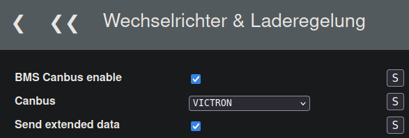
Send extended data only works with dbus-bsc-can. It is not recommended with CerboGX, whose limited performance can cause problems: in rare cases, an SoC of 0 % may be transmitted for about 30 seconds.
Venus OS Settings
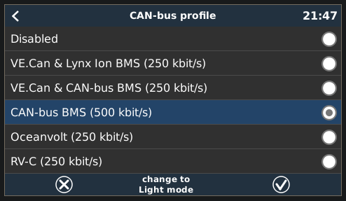
Open Menu / Settings / Services / can[0,1,2,3,...] / CAN bus profile.
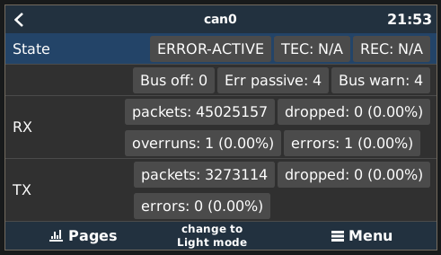
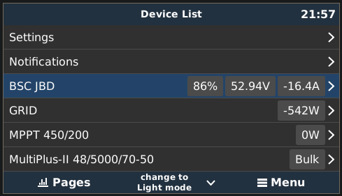
BSC Log When an Inverter Is Detected

Known Behaviour
Battery Discharges into the Grid
SoC reaches 100 %, then the battery discharges when switching to float voltage. This behaviour is independent of the BSC. With ESS and DC-coupled PV feed-in of excess enabled in Victron settings, the system attempts to lower voltage to float by discharging.
Previously suggested workaround: reduce the difference between float and absorption voltage to 0.4 V. To avoid repeated charging/discharging, do not set the BSC float-voltage SoC threshold too high, or it switches back to absorption and repeats the cycle.
Charge Current Limit (CCL) Is Ignored
When switching from absorption to float, the BSC sets CCL to 0 A. Victron may ignore this under some circumstances. With ESS DC-coupled PV feed-in of excess enabled, DVCC does not apply its PV-to-battery charge current limit, allowing export. Charge voltage limits still apply. Source: Victron.
Growatt SPF5000ES
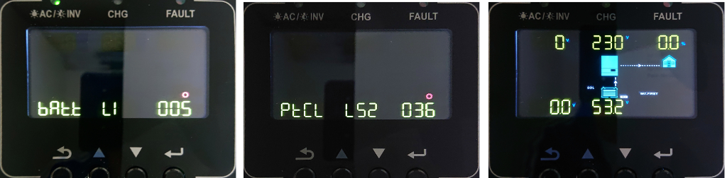
Connect via CAN. Select the Pylontech protocol (Deye...) in the BSC; Send extended data need not be enabled. On the inverter set Prg 005: LI, confirm, then set PRG 36: L52. SoC and other data should then be available.
Goodwe GW5048ES
Connect via CAN. Select Deye as the BSC CAN inverter protocol. Set the inverter battery to Goodwe 3x Secu-A5.4L; no inverter protocol setting is needed. Example BMS: 2× Seplos V2, configured for Pylontech and connected through BSC Serial 2.
Solis S5-EH1P & RHI 5G
CAN Connection
Connect H to H and L to L. Solis has no specified GND connection here.
| Signal | Connection | RJ45 wire colour (T568B) |
|---|---|---|
| CAN-L | Pin 5 | Blue/white |
| CAN-H | Pin 4 | Blue |
| CAN-GND | ? | ? |
Verify the Pinout
Colours shown follow T568B. Measure existing cables before connecting them. Incorrect mapping can cause malfunctions or damage.
BSC Settings
Under Settings / Inverter & Charge Control / General, select CANbus / Solis RHI, save, enable BMS CANbus enable, then save again.
Solis Settings
Open Advanced Settings / Storage Energy Set / Battery Select / Battery Module and select Pylon.
Deye SUN-12K-SG04LP3-EU & SUN-20K-SG05LP3
CAN Connection
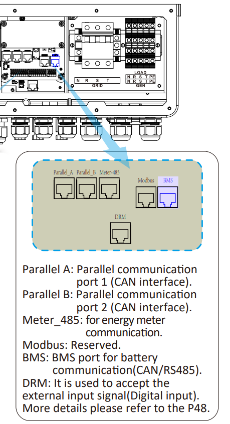
Use the inverter's BMS Port (manual page 10). Take three conductors from a standard network cable to the BSC CAN screw terminals: CAN-H to CAN-H, CAN-L to CAN-L, GND to GND.
| Signal | RJ45 connection | Wire colour (T568B) |
|---|---|---|
| CAN-H | Pin 4 | Blue |
| CAN-L | Pin 5 | Blue/white |
| CAN-GND | Pin 6 | Green |
Verify the Pinout
Colours shown follow T568B. Measure existing cables before connecting them. Incorrect mapping can cause malfunctions or damage.
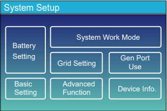
Inverter Settings
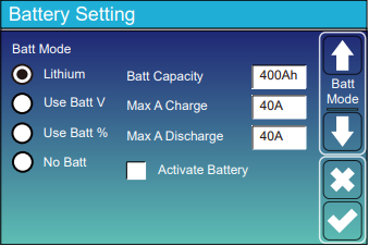
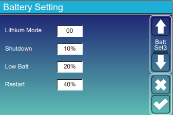
Set Bat Set 1 / Batt Mode: Lithium and Bat Set 3 / Lithium Mode: 00.
BSC Settings
Under Settings / Inverter & Charge Control / General, enable BMS CANbus enable, select Pylontech for CANbus protocol and Serial 2 for data source (master).